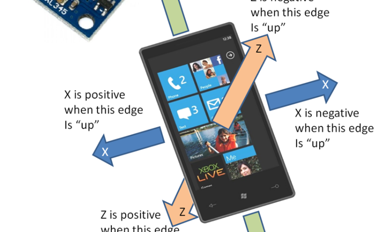
راه اندازی ماژول شتاب سنج ADXL345 با آردوینو
شرح ماژول ADXL345:
ADXL345 یک شتاب سنج 3 محوره با مصرف انرژی کم می باشد که دقت اندازه گیری بالای دارد (13 بیت) و تا 16g قابلیت اندازه گیری دارد. خروجی دیجیتال این شتاب سنج به صورت 16 بیتی می باشد. برای دسترسی یه آن می توان از ارتباط SPI یا I2C استفاده کرد. ADXL345 برای اندازه گیری شتاب استاتیک جاذبه در کاربرد های تشخیص شیب و شتاب پویا ناشی از حرکت یا شوک مناسب می باشد. حالت های مختلف اندازه گیری در ADXL345 موجود می باشد مثل تشخیص وجود یا عدم وجود حرکت تشخیص شتاب در هر محور که بیش از مقدار تنظیم شده باشد قابلیت تشخیض تپ و سنجش سقوط آزاد اگر دستگاه در حال سقوط آزاد باشد. این عملکردها را می توان به وسیله یک یا دو پین و وقفه خارجی پیاده سازی کرد.
ویژگی ها :
- ولتاژ تغذیه 2.0 تا 3.6 ولت
- مصرف بسیار کم: 40uA در حالت اندازه گیری و 0.1uA در استندبای @2.5V
- تشخیص تپ یا دابل تپ
- تشخیص سقوط آزاد
- اینترفیس SPI و I2C
دانلود ها:
اتصال ماژول ADXL345 به آردوینو:
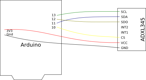
در این قسمت به نحوه اتصال بورد ADXL345 به آردوینو می پردازیم در جدول پایین نحوه اتصال هر پین نوشته شده است.
| Arduino Pin | ADXL345 Pin |
| 10 | CS |
| 11 | SDA |
| 12 | SDO |
| 13 | SCL |
| 3V3 | VCC |
| Gnd | GND |
و به صورت تصویری
کد ساده برای شروع کار با ADXL345:
//Add the SPI library so we can communicate with the ADXL345 sensor
#include <SPI.h>

//Assign the Chip Select signal to pin 10.
int CS=10;

//This is a list of some of the registers available on the ADXL345.
//To learn more about these and the rest of the registers on the ADXL345, read the datasheet!
char POWER_CTL = 0x2D;	//Power Control Register
char DATA_FORMAT = 0x31;
char DATAX0 = 0x32;	//X-Axis Data 0
char DATAX1 = 0x33;	//X-Axis Data 1
char DATAY0 = 0x34;	//Y-Axis Data 0
char DATAY1 = 0x35;	//Y-Axis Data 1
char DATAZ0 = 0x36;	//Z-Axis Data 0
char DATAZ1 = 0x37;	//Z-Axis Data 1

//This buffer will hold values read from the ADXL345 registers.
char values[10];
//These variables will be used to hold the x,y and z axis accelerometer values.
int x,y,z;

void setup(){
  //Initiate an SPI communication instance.
  SPI.begin();
  //Configure the SPI connection for the ADXL345.
  SPI.setDataMode(SPI_MODE3);
  //Create a serial connection to display the data on the terminal.
  Serial.begin(9600);

  //Set up the Chip Select pin to be an output from the Arduino.
  pinMode(CS, OUTPUT);
  //Before communication starts, the Chip Select pin needs to be set high.
  digitalWrite(CS, HIGH);

  //Put the ADXL345 into +/- 4G range by writing the value 0x01 to the DATA_FORMAT register.
  writeRegister(DATA_FORMAT, 0x01);
  //Put the ADXL345 into Measurement Mode by writing 0x08 to the POWER_CTL register.
  writeRegister(POWER_CTL, 0x08);  //Measurement mode
}

void loop(){
  //Reading 6 bytes of data starting at register DATAX0 will retrieve the x,y and z acceleration values from the ADXL345.
  //The results of the read operation will get stored to the values[] buffer.
  readRegister(DATAX0, 6, values);

  //The ADXL345 gives 10-bit acceleration values, but they are stored as bytes (8-bits). To get the full value, two bytes must be combined for each axis.
  //The X value is stored in values[0] and values[1].
  x = ((int)values[1]<<8)|(int)values[0];
  //The Y value is stored in values[2] and values[3].
  y = ((int)values[3]<<8)|(int)values[2];
  //The Z value is stored in values[4] and values[5].
  z = ((int)values[5]<<8)|(int)values[4];

  //Print the results to the terminal.
  Serial.print(x, DEC);
  Serial.print(',');
  Serial.print(y, DEC);
  Serial.print(',');
  Serial.println(z, DEC);
  delay(10);
}

//This function will write a value to a register on the ADXL345.
//Parameters:
//  char registerAddress - The register to write a value to
//  char value - The value to be written to the specified register.
void writeRegister(char registerAddress, char value){
  //Set Chip Select pin low to signal the beginning of an SPI packet.
  digitalWrite(CS, LOW);
  //Transfer the register address over SPI.
  SPI.transfer(registerAddress);
  //Transfer the desired register value over SPI.
  SPI.transfer(value);
  //Set the Chip Select pin high to signal the end of an SPI packet.
  digitalWrite(CS, HIGH);
}

//This function will read a certain number of registers starting from a specified address and store their values in a buffer.
//Parameters:
//  char registerAddress - The register addresse to start the read sequence from.
//  int numBytes - The number of registers that should be read.
//  char * values - A pointer to a buffer where the results of the operation should be stored.
void readRegister(char registerAddress, int numBytes, char * values){
  //Since we're performing a read operation, the most significant bit of the register address should be set.
  char address = 0x80 | registerAddress;
  //If we're doing a multi-byte read, bit 6 needs to be set as well.
  if(numBytes > 1)address = address | 0x40;

  //Set the Chip select pin low to start an SPI packet.
  digitalWrite(CS, LOW);
  //Transfer the starting register address that needs to be read.
  SPI.transfer(address);
  //Continue to read registers until we've read the number specified, storing the results to the input buffer.
  for(int i=0; i<numBytes; i++){
    values[i] = SPI.transfer(0x00);
  }
  //Set the Chips Select pin high to end the SPI packet.
  digitalWrite(CS, HIGH);
}
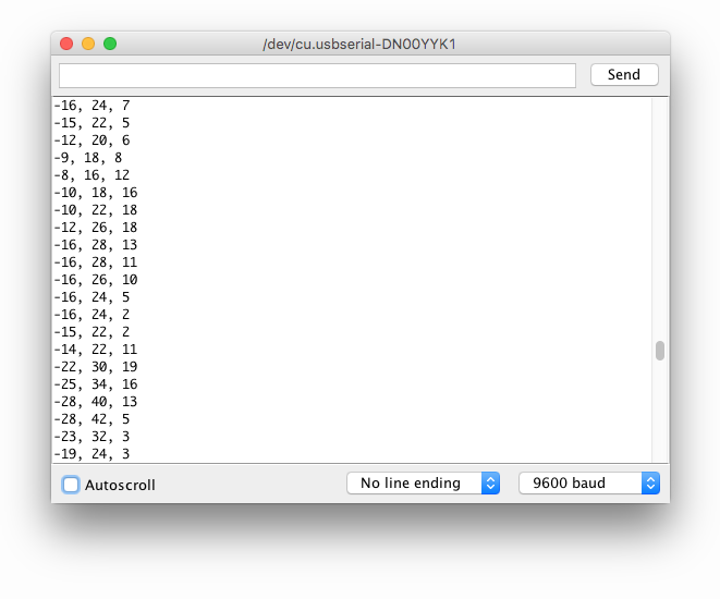
بعد از آپلود کد روی برد از طریق پورت سریال این خروجی را می توانید ببینید.

با سلام . از زحمات شما بسیار متشکر هستم و مطا لب در سایت بسیار آموزنده می باشد .
با سلام و تشکر از زحمات شما در صورت امکان راه اندازی این برنامه رو با avr و بسکام هم توضیح بدید با تشکر